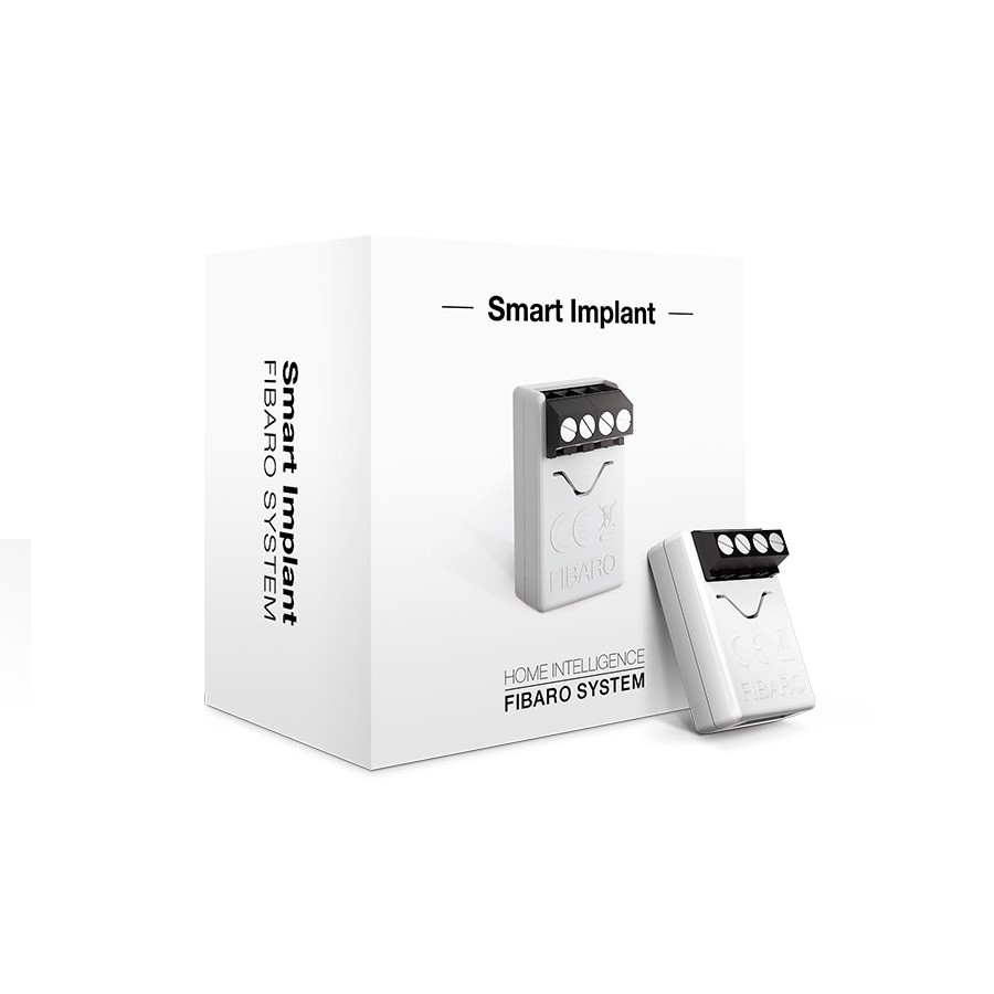
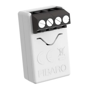
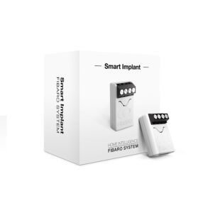
FIBARO Z Wave Implant
The FIBARO Z Wave Implant allows to enhance the functionality of wired sensors and other devices by adding Z-Wave network communication.
You can connect binary sensors, analog sensors, DS18B20 temperature sensors or DHT22 humidity and temperature sensor to report their readings to the Z-Wave controller.
The FIBARO Z Wave Implant can also control devices by opening/closing output contacts independently of the inputs.
PRODUCT FEATURES
Supports Z-Wave network Security Modes: S0 with AES-128 encryption and S2 Authenticated with PRNG-based encryption.
- Works as a Z-Wave signal repeater.
- Allows for connecting sensors:
- 6 DS18B20 sensors,
- 1 DHT sensor,
- 2 2-wire analog sensor,
- 2 3-wire analog sensor,
- 2 binary sensors.
- Built-in temperature sensor.
This product works with:
- Fibaro Home Centre 2/3/Lite
Please note: Before installation
- Connect only in accordance with one of the diagrams
- The device is powered with secure voltage; nevertheless, the user should be extra careful or should commission the installation to a qualified person
- Do not connect devices which are not compliant with the specification
- Do not connect other sensors than DS18B20 or DHT22 to SP and SD terminals
- Do not connect sensors to SP and SD terminals with wires longer than 3 meters
- Do not load the device outputs with a current exceeding 150mA
- Every connected device should be compliant with the relevant safety standards
- Unused lines should be left insulated
Tips for arranging the antenna:
Locate the antenna as far from metal elements as possible (connecting wires, bracket rings, etc.) in order to prevent interferences, Metal surfaces in the direct vicinity of the antenna (e.g. flush mounted metal boxes, metal door frames) may impair signal reception!
Do not cut or shorten the antenna – its length is perfectly matched to the band in which the system operates.
Make sure no part of the antenna sticks out of the wall switch box.
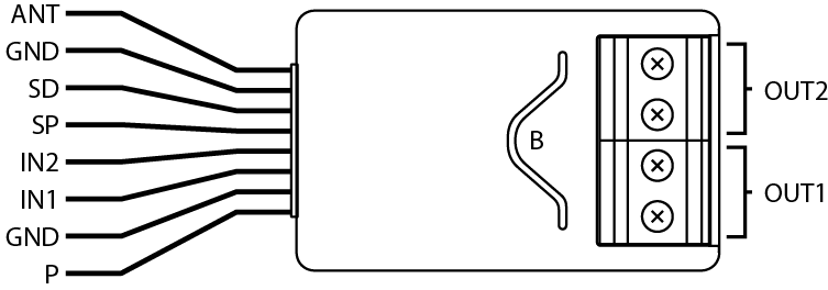
ANT (black) – antenna
GND (blue) – ground conductor
SD (white) – signal conductor for DS18B20 or DHT22 sensor
SP (brown) – power supply conductor for DS18B20 or DHT22 sensor (3.3V)
IN2 (green) – input no. 2
IN1 (yellow) – input no. 1
GND (blue) – ground conductor
P (red) – power supply conductor
OUT1 – output no. 1 assigned to input IN1
OUT2 – output no. 2 assigned to input IN2
B – service button (used to add/remove the device)
ADDITIONAL RESOURCES
TECHNICAL SPECIFICATIONS
|
RF Protocol
|
Z‐Wave (Multilevel Command Class)
|
|
RF Frequency
|
921.42Mhz ‐ AU/NZ approved RF for Z‐wave
|
|
Z‐Wave device type
|
Z-Wave binary sensor, slave
|
|
Power
|
9 – 30V DC ± 10%
|
|
Max. Current of Outputs
|
150mA
|
|
Operation Range
|
Up to 20m indoors with no obstacles
|
|
Application
|
Indoor use only
|
|
Measurement Range
|
-55C ~ 126°C
|
|
Operation Temperature
|
0 ~ 40 °C
|
|
Storage Temperature
|
‐10 ~ 80 °C
|
|
Weight
|
10g
|
|
Compliance
|
TBA
|
|
Regulatory Compliance Mark
|
RoHS 2011/65/EU RED 2014/53/EU
|
|
Dimensions
|
(LxWxH) 29 x 18 x 13 mm
|
Related products
Smart Sensors

